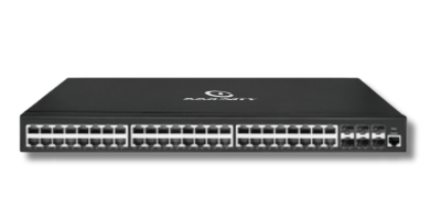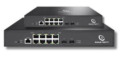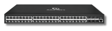
NetForce is the switching brand of Immunity Networks & Technologies Pvt Ltd, an Indian networking OEM founded in 2009, with a manufacturing facility at Sanand GIDC in Gujarat and a head office at Powai, Mumbai. The family covers Layer 2 managed access switching and Layer 3 switching for aggregation and core roles, designed to work alongside NetWave Wi-Fi access points, NetGuard controllers, NetBeam optics and NetCloud Central. This page is the starting point for network engineers, IT heads and system integrators who are specifying a switching layer and want to understand the design decisions before they look at any individual model.
Most network projects in India are described in terms of the things users can see. A hotel talks about guest Wi-Fi. A hospital talks about tablets at the nursing station. A factory talks about handheld scanners on the shop floor. A college talks about hostel connectivity. Yet in almost every one of those projects, the component that determines whether the outcome is good or bad is the switching layer sitting quietly in the rack. Access points can only carry what the switch feeds them. Cameras can only stay online if power over the copper is stable. Segmentation between guest traffic and business traffic is enforced by VLANs configured on switches, not by wishful thinking. When a deployment underperforms, the root cause is frequently a switching decision taken twelve months earlier by someone who was told to save a little money on the access layer.
That is the reason this hub exists. Rather than pushing you straight into a model list, it explains the architecture first: where switches sit, what Layer 2 and Layer 3 actually do differently, how power budgets are planned, how uplinks are chosen, and what to insist on in writing from any vendor before you release a purchase order. Once those decisions are settled, choosing between the NetForce L2 managed switching line and the NetForce L3 line becomes straightforward, and the conversation with our engineers becomes a short one.
Immunity Networks has been building enterprise networking equipment in India since 2009. The switching, wireless, gateway and optics lines are designed to be deployed together, which means the questions a system integrator normally has to answer across three or four vendors, such as which optic is supported in which cage, or how a port profile maps to an SSID, can be answered by one engineering team. If you would prefer to skip the theory and describe your site, our engineers will size the switching layer with you directly.
Enterprise switching is usually drawn as three tiers. The mistake many buyers make is to treat those tiers as quality grades, where the core switch is the good one and the access switch is the cheap one. They are not grades. They are three different jobs, and a switch that is excellent at one of them may be entirely unsuitable for another.
The access layer is where users and devices physically plug in or where access points are mounted. Its job is to terminate many copper ports, deliver power over those ports where required, place each port into the correct VLAN, authenticate what connects, and hand the resulting traffic upstream. This is the layer that touches the most cables, sits in the most cupboards and gets the most abuse. It is also where port count and power planning matter more than raw forwarding numbers. Most of what an access switch does day to day is described on the NetForce L2 page.
The distribution layer aggregates several access switches, usually one per building or per floor group, and is normally where routing between VLANs begins. It is the natural place to apply policy: which subnets may talk to which, where traffic is prioritised, and where a guest network is kept firmly away from a finance network. In a single-building office this tier often merges with the core.
The core layer exists to move aggregated traffic quickly and predictably between distribution blocks and onward to the gateway. It is generally fibre-heavy and light on access ports. The NetForce L3 page covers the models that are positioned for distribution and core roles, and our switching and routing solution page describes how these tiers are usually combined in Indian campus and multi-site designs.
A practical rule: decide the tier a switch will occupy before you decide anything else. A switch bought for a core role and then used as an access switch will leave you short of ports and short of power. A switch bought for an access role and pushed into a core will bottleneck the whole site. If you are unsure which tier your requirement falls into, describe the building and the device count to us and we will map it out.
NetForce is organised into two managed lines. The Layer 2 line is built for access-layer duty, and the Layer 3 line adds routing for aggregation and core duty. Model designations that appear across the site include L2-D486, L2-D822 and L2-E822 on the Layer 2 side, and L3-C122, L3-C244, L3-C802, L3-D244, L3-D486, L3-E244 and L3-E486 on the Layer 3 side. Availability, port configuration and feature sets differ by model and can change between production runs, so please ask us to confirm current specifications in writing for the specific model you intend to quote or tender.
Layer 2 managed switching for the edge of the network, where access points, cameras, handsets and workstations connect. VLAN segmentation, port-based access control, traffic prioritisation and Power over Ethernet on the models that offer it. Read the detail on the NetForce L2 page.
Layer 3 switching for distribution and core roles, where traffic has to move between subnets rather than merely within one. Inter-VLAN routing, access control policy and fibre uplink options. Read the detail on the NetForce L3 page.
Switching rarely arrives alone. NetForce is designed to sit under NetWave Wi-Fi access points, behind NetGuard controllers, linked by NetBeam optics and visible through NetCloud Central.
Because all four product lines come from the same OEM, the integration questions that normally consume the first two weeks of a project have shorter answers. Which optic is qualified in which uplink cage is a question we can answer directly rather than referring you to a third-party compatibility matrix. How a port profile on a switch maps to an SSID on an access point is a single design conversation. For larger multi-site rollouts, our enterprise networking page describes how the pieces are typically staged, and our partner programme covers how system integrators are supported commercially and technically.
This is the question we are asked most often, and it is asked in the wrong form more often than not. Buyers tend to ask "which is better, L2 or L3?" The honest answer is that they do different jobs, and a well-designed network usually contains both. The useful question is: at which point in my network does traffic need to cross from one subnet to another, and what device should do that crossing?
A Layer 2 managed switch forwards Ethernet frames within a broadcast domain using MAC addresses, and divides the physical box into logical networks using VLAN tags. It is very good at keeping a hundred devices on one floor talking to each other efficiently, at keeping the guest VLAN separate from the corporate VLAN, at powering devices over the same cable that carries their data, and at refusing to admit devices that have not authenticated. What it does not do is move a packet from one subnet into another. That job goes upstream.
A Layer 3 switch does everything a Layer 2 switch does and additionally routes between subnets in hardware. The practical effect is that traffic between, say, the clinical VLAN and the imaging VLAN in a hospital, or between the warehouse management VLAN and the office VLAN in a distribution centre, can be routed inside the building instead of travelling all the way to a gateway and back. That reduces the load on the gateway, reduces the distance packets travel and gives you a natural place to enforce policy between segments.
One: how many VLANs will actually exist, and will they need to talk to each other? If you are running one flat network, or two VLANs that never need to exchange traffic, Layer 2 across the site is sufficient and simpler to operate. If you are planning six or eight segments that genuinely need controlled communication between them, routing has to happen somewhere.
Two: how much inter-subnet traffic is there, and where is it going? A small office where inter-VLAN traffic is a handful of print jobs and a shared drive can route at the gateway without noticing. A campus where student devices constantly reach servers in a different subnet cannot. Estimate the volume honestly rather than assuming.
Three: is the gateway already doing enough? Many Indian sites route all inter-VLAN traffic through a firewall because the firewall was there first. That works until the firewall becomes the busiest device in the building. If your gateway or controller is also handling internet policy, content filtering and remote access, adding all internal routing to its workload is a decision to make deliberately, not by default.
Four: what happens in year three? Switching is a five to seven year purchase in most Indian enterprises. A site with two VLANs today and a plan to add IoT, surveillance and guest access over three years will need routing eventually. Buying Layer 3 at the aggregation point now is usually cheaper than replacing the aggregation point later.
Five: who will operate it? Layer 3 brings routing configuration, and routing configuration brings an operational skill requirement. If the site is unmanned and supported remotely by a small team, a design with routing concentrated at one clearly documented point is easier to live with than routing scattered across many devices. Our guide to choosing an enterprise switch works through this trade-off in more depth.
For the majority of the campuses, hotels, hospitals and plants we work on in India, the answer is a mixed design: Layer 2 access switches in every floor cupboard, feeding Layer 3 switches at the building aggregation point, which in turn connect to the gateway. Access ports stay simple and replaceable. Routing and policy live in a small number of well-documented devices. Adding a new VLAN is a change at two places, not twenty. If your site does not fit that pattern, tell us why and we will work through the alternative with you.
Power over Ethernet is the feature most often specified casually and regretted later. The phrase "PoE switch" tells you almost nothing on its own. What matters is how much power the switch can deliver in total, how much any single port can deliver, and how those two numbers interact with the devices you intend to connect. Because we cannot responsibly publish a wattage figure that may differ between models and production runs, this section explains the concept, and you should ask us to confirm current specifications in writing for the specific model you are considering.
The method we recommend is unglamorous and effective. List every device that will draw power from the switch. Take the manufacturer's stated maximum draw for each, not the typical draw, because typical draw is measured under conditions your site may not match. Add an allowance for cable loss, which grows with distance. Sum the result. Then compare that sum against both the per-port class and the total budget of the candidate model, and leave headroom, because the device list on day one is never the device list in year two. Outdoor cameras with heaters, high-density access points and devices with attached peripherals are the usual causes of an overrun.
Power classes and terminology are covered in our explainer on PoE, PoE+ and PoE++, which is worth reading before you finalise a bill of materials. If your device mix includes anything unusual, send us the list and we will work through the arithmetic with you rather than leaving you to discover the problem at commissioning. The same exercise matters for wireless projects, since access point placement drives both the switch port count and the power draw; our campus wireless page and the NetWave access point range are the usual companions to this conversation.
Access ports are usually copper because the devices they serve are copper. Uplinks are a separate decision, and one that deserves more thought than it usually gets. The choice between copper and fibre for the link between an access switch and its aggregation point is driven by distance, by the electrical environment, by future bandwidth expectations and by what is already installed in the building.
Distance is the most common deciding factor. Copper Ethernet has a hard practical limit that fibre does not, which is why any run between buildings, between distant blocks of a campus, or up a tall structure ends up on fibre. Electrical environment matters in industrial settings, where fibre's immunity to electromagnetic interference and its lack of a shared electrical path between buildings solve problems that copper creates. Bandwidth expectation matters because an uplink is the aggregation of everything below it, and an uplink that is adequate today is the first thing to saturate when device counts grow. Our comparison of fibre versus copper in enterprise networks covers the trade-offs in detail.
Where fibre uplinks are used, the optics themselves are a component decision that affects both cost and supportability. Mixing optics from several sources across a large estate creates a spares problem and a diagnostics problem: when a link degrades, you want to know whether the optic, the fibre or the port is at fault, and a consistent optic estate makes that much faster. The NetBeam optics range is designed to be specified alongside NetForce switching for exactly that reason. Ask us to confirm in writing which optic types are supported in the uplink cages of the specific switch model you are quoting, because this varies by model.
A related point worth raising early with any vendor: cabling standards. A switch specified correctly will still disappoint if the structured cabling feeding it is of a lower category than the port speed requires, or if patch cords have been sourced casually. On several projects the single most valuable thing our engineers have done is to test the existing cabling before the switches were ordered. If you are retrofitting an older building, plan for that survey.
The same three-tier model looks different in a hotel, a hospital, a warehouse and a factory, because the devices, the cable routes and the tolerance for downtime are different. These are the patterns we see most often in India.
Per-floor access switching feeding corridor access points, with guest traffic segmented from property management and back-of-house systems. Cable routes are constrained and cupboard space is scarce, so port density and quiet operation matter. See hotel Wi-Fi solutions.
Strict segmentation between clinical systems, administrative networks, guest access and surveillance, with routing between segments controlled deliberately. Downtime tolerance is low and change windows are short. See hospital Wi-Fi solutions.
Long cable runs across high-bay space, access points mounted at height, and scanners that stop the operation when they drop. Fibre uplinks between blocks are common. See warehouse Wi-Fi solutions.
Electrically noisy environments, separation between operational technology and information technology networks, and equipment that may sit outside a comfortable cupboard. See manufacturing plant Wi-Fi.
Many buildings, seasonal load peaks, hostels, laboratories and open lawns. This is where a clean three-tier design pays for itself most visibly. See campus wireless and switching and routing.
Branches that must be configured identically and supported remotely, where consistency of model and firmware across sites matters more than any single specification. See enterprise networking and NetCloud Central.
Indian enterprise and government buyers are increasingly asked to demonstrate that the equipment they have purchased meets domestic regulatory requirements. Depending on the product category and the procurement route, the requirements that come up most often are MTCTE registration under the mandatory testing and certification regime, TEC-related requirements, and WPC clearance where radio equipment is involved. Tender documents may also ask about local content declarations, testing reports and portal listings.
Our advice here is deliberately even-handed and applies to every vendor including us: ask for certification status in writing, per model, and dated. Certification is granted against specific models and specific test reports, and it has validity periods. A statement that a brand is certified is not the same as a statement that the model you are about to order is currently certified. A responsible supplier will have no difficulty putting that in writing on letterhead against the exact model designation and the exact configuration you intend to buy. If a supplier hesitates, that is useful information. You can read more about how we handle this on our certifications page, and you should request current written confirmation for your specific model from our team rather than relying on any web page, including this one.
The same discipline applies to specifications. Port configurations, power budgets, uplink options and supported feature sets can differ between models and between production runs. Nothing on this hub page should be treated as a specification commitment. Ask us to confirm current specifications in writing for the specific model, in the exact configuration and quantity you intend to order, and use that written confirmation as your tender annexure rather than a marketing page.
For system integrators, our partner programme covers pre-sales design support, documentation packs for tender submissions and the commercial arrangements that go with them. Because design, manufacturing and support are all handled in India, escalation on a documentation query does not involve waiting for a different time zone to wake up.
When a switching requirement arrives on our desk as a clean brief, the quotation is accurate and the project runs on schedule. When it arrives as "we need 24-port switches for four floors", the first two weeks are spent asking questions. Here is what a good brief contains, and what we would ask you for anyway.
The device inventory. Not just how many ports, but what plugs into them: how many access points, how many cameras, how many handsets, how many fixed workstations, how many controllers or sensors, and which of those need power from the switch. This single list drives port count, power budget and often the layer decision.
The building layout and cable routes. Where the cupboards are, how far the longest run is, whether there is fibre between blocks, and whether the cabling is new or inherited. Distance decides copper versus fibre; inherited cabling decides whether a survey is needed first.
The segmentation plan. Which VLANs will exist, which must be able to reach which, and which must be kept strictly apart. This is the input to the Layer 2 versus Layer 3 decision described above, and it is far better settled on paper than discovered during commissioning.
The management and support model. Who will operate the network day to day, whether sites are staffed, and whether central visibility through something like NetCloud Central is required or optional. A design that a two-person team can support looks different from one supported by a large NOC.
The growth expectation. Device counts three years out, planned building expansion, and any known projects such as a surveillance upgrade or a wireless refresh. Headroom bought at the time of purchase is cheap; headroom retrofitted later is not.
The procurement route and documentation needs. Direct purchase, tender, or through a system integrator, and what certification and local content documentation the process will demand. Flag this early so the paperwork moves in parallel with the technical design rather than after it.
Send us those six things and we will come back with a switching design, a bill of materials and written specification confirmation for each model proposed. If you would rather talk it through first, our engineers are based in India and are happy to work from a sketch.
Describe your site, your device inventory and your segmentation plan. Our India-based engineering team will propose a switching layer across the NetForce L2 and NetForce L3 lines, confirm current specifications in writing for each model proposed, and set out how it fits with your wireless, gateway and optics requirements.
A Layer 2 switch forwards traffic within a network segment using MAC addresses and separates the box into logical networks using VLANs. A Layer 3 switch does that and additionally routes traffic between subnets in hardware. In practice, Layer 2 belongs at the access layer where devices connect, and Layer 3 belongs at the point where traffic must cross between segments, typically the distribution or core layer. The decision flow in the section above walks through it, and the L2 and L3 pages cover each line in detail.
Model designations that appear across the site include L2-D486, L2-D822 and L2-E822 in the Layer 2 line, and L3-C122, L3-C244, L3-C802, L3-D244, L3-D486, L3-E244 and L3-E486 in the Layer 3 line. Port configurations, power budgets and supported features differ by model. Please ask us to confirm current specifications in writing for the specific model you intend to quote, rather than relying on a summary page.
List every device that will draw power, take each manufacturer's stated maximum draw rather than the typical draw, add an allowance for cable loss on long runs, and sum the result. Then check that sum against two separate limits on the candidate switch: the maximum a single port can deliver, and the total the switch can deliver across all ports at once. Leave headroom for growth. Our explainer on PoE, PoE+ and PoE++ covers the classes, and we are glad to check the arithmetic with you.
Distance is usually the deciding factor: runs between buildings or across large sites go on fibre because copper Ethernet has a hard practical distance limit. Electrically noisy environments such as plants favour fibre as well. Within a single floor, copper uplinks are often sufficient. Bandwidth expectation matters too, since an uplink carries everything beneath it. Our comparison of fibre versus copper sets out the trade-offs, and the NetBeam optics range is specified alongside NetForce switching.
Yes, the lines are designed to be deployed together. NetForce switching sits under NetWave Wi-Fi access points, behind NetGuard controllers, connected by NetBeam optics, with central visibility through NetCloud Central. Because everything comes from one OEM, integration questions have a single point of answer.
Indian buyers increasingly need to demonstrate MTCTE registration, TEC-related requirements and, where radio equipment is involved, WPC clearance. Our advice applies to every vendor: ask for certification status in writing, per model, dated, against the exact configuration you intend to order. Certification is granted against specific models and has validity periods, so a general brand-level claim is not sufficient for a tender file. See our certifications page and request current written confirmation from our team.
Immunity Networks & Technologies Pvt Ltd was founded in 2009 and operates a manufacturing facility at Sanand GIDC in Gujarat, with its head office in Powai, Mumbai. Design, manufacturing and support are handled in India, which is why documentation queries and technical escalations are answered locally rather than routed overseas. Our partner programme covers how system integrators are supported.
Yes. Send us the device inventory, the building layout and cable routes, the segmentation plan, the management model, the growth expectation and the procurement route, and our engineers will propose a switching layer across the L2 and L3 lines with written specification confirmation for each model. If you would rather start with a conversation, contact us and describe the site, or pull background reading from downloads.