Make-in-India OEM  •  Enterprise WiFi 6 · Switching · Security · AIOps Cloud
HomeProductsNetBeam Optics
NetBeam Optics · SFP, SFP+ and fibre components

NetBeam Optics: transceivers and fibre components for Indian enterprise networks

NetBeam is the optical transceiver and fibre component family from Immunity Networks & Technologies Pvt Ltd, an Indian networking OEM manufacturing at Sanand GIDC in Gujarat since 2009. NetBeam modules are built to plug into our own NetForce switching platforms and into the mixed-vendor estates that most Indian campuses actually run. This page explains what the family covers, how coding and compatibility work, what DDM tells you, and how to write an optics specification that will not fall apart at commissioning.

The cheapest component in the network, and the one that fails the project

Optics are a rounding error on a campus network BOQ and the single most common reason a link does not come up on commissioning day. A switch pair can be perfectly configured, the fibre can be terminated cleanly, the VLANs can be correct — and the port stays down because the transceiver on one end reports a vendor code the far-end platform refuses to accept, or because someone has put a single-mode module on a multi-mode patch cord, or because the two ends are simply not the same optical type. None of these are exotic problems. They are the ordinary friction of buying optics separately from switches, which is exactly what almost every Indian enterprise ends up doing once the original warranty period is over and the OEM's own module prices have become uncomfortable.

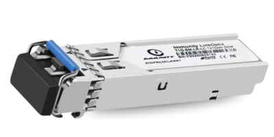
NetBeam exists to remove that friction. The family covers SFP and SFP+ pluggable transceivers, direct-attach copper assemblies, fibre patch cords and passive fibre components, and the media conversion pieces that campuses still need at the edges of a build. The design intent is simple: a module you order for a specific switch model, with the correct coding applied before it ships, arriving with its optical parameters documented, so the port comes up the first time it is inserted. Because we are the OEM for the NetForce switch line, we can validate NetBeam modules against our own Layer 2 access switches and Layer 3 aggregation and core switches directly, and we can tell you honestly where third-party interoperability has been tested and where it has not.

If you want the background theory before the product detail, our engineering team wrote a longer explainer that ranks well for exactly these questions: the SFP and SFP+ transceivers buyer's guide. It covers form factors, coding, DDM and reach selection in more depth than a product page reasonably can, and it is written for engineers rather than procurement.

Form factors and reach tiers, explained plainly

Two things determine which module you need: the form factor the switch cage accepts, and how far the light has to travel. The form factor is a mechanical and electrical question. SFP and SFP+ share the same physical cage, so an SFP module will usually seat in an SFP+ port, but the reverse is not dependable and the port must be configured for the speed you intend to run. As a general industry convention, SFP modules are associated with gigabit-class links and SFP+ modules with 10-gigabit-class links; higher-speed pluggables such as SFP28 and QSFP families use different cages and are a separate conversation. Reach is an optical question, and it is governed by the fibre type, the transmit power and receive sensitivity of the module pair, and the total loss budget of the run including every connector, splice and patch panel in between.

The diagram below sets out the relationship in the way most engineers think about it during design: what physically plugs in, and roughly how far each tier of optics is intended to carry a signal. The tiers are qualitative on purpose — actual reach on any given link is a loss-budget calculation, not a number printed on a box.

Transceiver form factors and reach tiers A diagram showing SFP and SFP+ pluggable form factors sharing a common cage, alongside direct-attach copper assemblies, mapped against four qualitative reach tiers: in-rack, within a building, across a campus, and between sites. Form factor SFP Gigabit-class, industry norm Duplex LC or single-fibre BiDi optical interface SFP+ 10-gigabit-class, industry norm Same cage as SFP; port speed must be set correctly Direct-attach copper Fixed assembly, both ends integrated Reach tier In-rack / adjacent rack Typically served by direct- attach copper assemblies. Lowest cost per link. Within a building Riser and floor links, usually multi-mode fibre on existing building infrastructure. Across a campus Building-to-building runs. Single-mode is the usual choice for new builds. Site to site Leased or owned dark fibre. Loss budget must be measured, not assumed. Shorter reach, lower optical budget Longer reach, tighter budget discipline Tiers shown qualitatively. Actual supported distance on any link is a loss-budget calculation over the installed fibre, including connectors, splices and patch panels. Ask us to confirm current specifications and compatibility in writing.

What the NetBeam family covers

Capability, not a catalogue. Exact models, optical parameters and availability change; ask us to confirm current specifications and compatibility in writing for your specific switch platform and link.

SFP transceivers

Gigabit-class pluggable optics for access uplinks, fibre-to-the-desk aggregation, and the long tail of existing switch estates that will run at gigabit for years yet. Available in duplex and single-fibre bidirectional variants, with coding applied for the target platform. These are the modules that populate uplink ports on NetForce L2 access switches across a floor.

SFP+ transceivers

Ten-gigabit-class optics for distribution and core uplinks, server-facing links and inter-building runs. This is where most campus refresh projects now sit, because access switch uplink capacity has become the constraint rather than the access ports themselves. Pairs with NetForce L3 switching in aggregation and core roles.

Direct-attach assemblies

Fixed copper assemblies for short in-rack and adjacent-rack connections between switches, or between switches and servers. Lower cost per link than a transceiver pair plus patch cord, with fewer connector faces to contaminate — but no flexibility once installed, and length must be specified accurately at order stage.

Fibre patch cords and pigtails

Single-mode and multi-mode patch cords, pigtails and adaptors in the connector types Indian campuses actually have installed. Cord quality and end-face cleanliness matter more than most BOQs acknowledge; a contaminated ferrule can cost more optical budget than the extra hundred metres of run you were worried about.

Media conversion and edge pieces

Copper-to-fibre conversion for the awkward corners of a campus: an outlying gate house, a plant room, a legacy device that will never speak fibre natively. Frequently deployed alongside NetWave access points at the far edges of an outdoor campus wireless footprint.

Coding to your platform

Modules programmed with the vendor identification your switch expects, specified per line item on the order. Tell us the exact switch model and firmware and we will code accordingly — and tell you in writing where a given combination has been validated and where it has not.

Third-party compatibility, coding and vendor lock-in

This is the question Indian buyers ask first, and it deserves a direct answer rather than a marketing one. Every pluggable transceiver carries a small EEPROM containing identification data — a vendor name, a part number, and in many implementations a checksum or signature that the host switch reads when the module is inserted. Some switch platforms will bring up any module that presents valid optical parameters. Others check the vendor field and either refuse to enable the port outright, or enable it while logging a warning and declining to support the link. A few sit in between, requiring an explicit configuration command to permit unsupported optics. None of this is defined by the multi-source agreements that standardise the modules themselves; it is a commercial policy implemented in firmware.

The practical consequence is vendor lock-in on a component that is otherwise a commodity. Enterprises that bought a switch estate five years ago frequently find that replacing a failed uplink module means paying a substantial multiple of the market price, or waiting on an import lead time, because the original OEM's coding is the only thing the port will accept. Over a campus with hundreds of fibre uplinks, that is a material line in the operating budget and a real availability risk when a module fails at three in the morning.

Coding a third-party module for a specific host platform is the standard industry response, and it is entirely legitimate — the module is programmed to identify itself in the format the host expects, so the port comes up and the optics behave as the standards require. What matters is doing it accurately. Coding is per platform and sometimes per firmware family, so "code it for a Cisco" or "code it for an Aruba" is not a specification; the switch model and software version are. We ask for both at order stage, and where we have validated a particular combination against real hardware we will say so. Where we have not, we will say that too, and we will tell you what testing we can arrange before you commit to volume. Ask us to confirm current specifications and compatibility in writing — for NetBeam and, frankly, for any vendor you evaluate.

The other route out of lock-in is to stop buying switches that impose it. The NetForce switching family is designed to accept standards-compliant optics without an artificial vendor gate, which means the optics decision stays a decision rather than becoming a tax. For organisations running a mixed estate, that matters most at the aggregation layer, where a handful of L3 switches carry a disproportionate share of the uplinks. Distribution partners who resell across several switch brands can hold NetBeam stock and code to order rather than carrying separate inventory per OEM; if that is your model, our partner programme is the place to start.

DDM and DOM: the diagnostics that save you a site visit

Digital diagnostics monitoring — called DDM or DOM depending on whose documentation you are reading — is a facility defined in the relevant multi-source agreements that allows a transceiver to report its own operating state to the host switch. The standard set of readings covers module temperature, supply voltage, laser bias current, transmit optical power and received optical power. The switch exposes these through its CLI and through SNMP, which means they can be polled, graphed and alarmed like any other network metric.

For an operations team, this is the difference between diagnosing a link and guessing at it. A link that is flapping intermittently is a very different problem depending on whether received power is sitting comfortably above the sensitivity threshold or hovering a fraction of a decibel over it. Falling receive power over weeks usually means a physical plant problem — a connector working loose, a cord under strain in a tray, contamination on an end face, or water ingress in an outdoor duct. Rising bias current at stable temperature typically points at a laser approaching end of life. Neither of those is visible from the port counters alone, and both are cheap to fix if you catch them before the link drops.

The operational win is that DDM turns optics from a reactive component into a monitored one. Poll receive power on every fibre uplink, set a threshold a sensible margin above the documented sensitivity floor, and you get an alarm weeks before an outage rather than a ticket after it. When those readings feed into a central monitoring view alongside switch and wireless telemetry — the kind of consolidated picture NetCloud Central is built to provide, and that NetGuard controllers contribute to on the wireless side — a slow-degrading fibre run in a service duct stops being an invisible risk. For an enterprise estate spread over multiple buildings, that visibility is usually worth more than the price difference between one module and another.

NetBeam modules are built to support digital diagnostics reporting; the precise parameter set and calibration approach vary by module type, so ask us to confirm current specifications and compatibility in writing for the models you intend to deploy. One caution worth stating: DDM readings are only as good as the calibration behind them, and a module that reports optimistic numbers is worse than one that reports none, because it will quietly consume your troubleshooting margin. That is a reasonable question to put to any optics supplier during evaluation.

Single-mode or multi-mode, and where optics sit in a campus

Multi-mode fibre has a wider core that allows light to travel along several paths simultaneously. Those paths have slightly different lengths, so the pulse spreads as it travels — modal dispersion — and this limits how far a given data rate can be carried before the receiver can no longer distinguish one bit from the next. Single-mode fibre has a much narrower core that supports essentially one propagation path, so the pulse holds its shape over far greater distances. As a general rule of the industry, single-mode reaches considerably further than multi-mode at any given data rate, while multi-mode optics have historically been cheaper because they use less precise light sources.

In Indian enterprise practice, the decision is usually made for you by what is already in the ground. Buildings wired ten or fifteen years ago are very likely to have multi-mode risers, and pulling new fibre through occupied floors is expensive and disruptive, so multi-mode optics are the pragmatic choice for in-building links. Inter-building campus runs and anything leaving the premises are almost always single-mode, and for new builds single-mode is increasingly specified even for in-building risers because it does not need to be replaced when the link speed rises again. The mistake to avoid is mixing them: a single-mode module launching into a multi-mode cord may light up and pass some traffic while performing unpredictably, which is a far harder fault to diagnose than a port that simply stays down.

The diagram below shows where each type of link typically sits in a campus topology, and where the transceivers physically live.

Where optics sit between switches across a campus A campus network topology diagram showing access switches in two buildings connected by multi-mode in-building risers to building distribution switches, which connect over single-mode campus fibre to a core switch pair in the main data room, with a further single-mode link out to a remote site. BUILDING A Access sw Access sw Distribution multi-mode riser BUILDING B Access sw Access sw Distribution CORE DATA ROOM Core switch A Core switch B single-mode campus fibre single-mode campus fibre REMOTE SITE Leased or owned dark fibre = transceiver pair (one at each end of every fibre link) = multi-mode, typically in-building = single-mode, campus and inter-site Both ends of a link must be the same optical type.

How to specify optics so the link comes up first time

Most optics failures at commissioning trace back to an under-specified purchase order. A BOQ line reading "10G SFP+ module, qty 48" contains almost none of the information needed to ship the right part. Here is what a supplier actually needs from you, and what you should expect back in writing.

The exact host platform on both ends. Switch model and software version for each end of the link, not just the brand. If one end is a NetForce L3 switch and the other is an incumbent third-party box, say so — that is the case where coding matters most and where a compatibility statement in writing is worth having on file.

The fibre you already have. Single-mode or multi-mode, the connector type at the patch panel, and ideally the measured loss on the run. If the fibre was tested at installation, dig out the OTDR or loss-test report. If it was not, budget for testing before you commit to long-reach optics; assumed distances have a way of being wrong by a factor that matters.

The real path length, not the map distance. Fibre follows ducts, risers and cable trays, not straight lines. A building-to-building run that measures two hundred metres on a site plan can easily be twice that in installed cable once vertical rises and slack loops at each end are counted.

Every connector and splice in the path. Each mated pair and each splice consumes optical budget. A run through three patch panels is a materially different link from the same distance run direct, and it is the cumulative loss that determines whether a given optic will work, not the metres alone.

Environment. Modules in an air-conditioned data room and modules in an unventilated roadside cabinet in Gujarat in May are not facing the same problem. Say where the equipment lives so the right temperature grade is quoted.

Diagnostics and monitoring expectations. If your NOC polls receive power — and it should — confirm that DDM support is part of the specification rather than assuming it.

Spares strategy. Decide the spare ratio at design stage and buy it with the project. Optics are small, cheap relative to a switch, and impossible to source at speed when a link fails on a holiday weekend. A sensible on-site spares holding costs less than one emergency procurement cycle.

Make in India, and what to ask about certification

Immunity Networks & Technologies has been building enterprise networking hardware in India since 2009, with manufacturing at Sanand GIDC in Gujarat and head office in Powai, Mumbai. For optics buyers, domestic manufacture and domestic stocking translate into two practical things: shorter replacement cycles when a module fails, and a support conversation conducted in the same time zone by people who can see the same test bench you are describing. When a coding question comes up, it is answered by an engineer who can put the module into the actual switch model rather than by a ticket queue on another continent. Public-sector and PSU tenders increasingly carry local content requirements as well, and it is reasonable to ask any supplier to state their position on that in writing rather than inferring it from a logo.

On certification, the honest guidance is procedural rather than promotional. Indian enterprise and government buyers increasingly require MTCTE registration, TEC approvals and, for anything with a radio, WPC clearance — and the applicable requirements differ by product category and change over time. Whichever vendor you are evaluating, including us, the correct step is to ask for written confirmation of certification status against the specific model numbers on your BOQ, with the certificate references, and to make that confirmation a condition of the purchase order rather than a post-award discovery. A supplier who is comfortable putting it in writing per model is telling you something useful. Our certifications and compliance page is where we set out our approach to these approvals and how to request current documentation for a given model.

The same discipline applies to warranty. Ask what the warranty period is, whether it is advance-replacement or return-to-base, what turnaround is committed, and who holds the stock the replacement will come from. Optics warranties are often quoted generously and supported thinly; the questions that matter are logistical, not contractual.

Send us your link list. We will tell you what to order.

Give our engineering team the switch models at both ends, the fibre type and the path details for each link, and we will come back with a specification, a compatibility position in writing, and a spares recommendation. If a combination has not been validated, we will say so rather than let you find out at commissioning.

Frequently asked questions

Will a third-party transceiver work in my existing switches?

Usually yes, provided it is coded correctly for the host platform and the optical type matches the far end. Pluggable transceivers are standardised by multi-source agreements, so the optics and electrical interface are common across manufacturers. What varies is the host switch firmware: some platforms accept any standards-compliant module, some check the vendor identification in the module EEPROM and refuse to bring the port up, and some enable the port but log a warning or withdraw support for the link. This is a commercial policy in firmware rather than a technical limitation. Tell us the exact switch model and software version at both ends and we will tell you what applies, and we will confirm the compatibility position in writing before you order.

What does "coding" a module actually mean, and is it legitimate?

Every pluggable module carries a small EEPROM holding identification data — vendor name, part number and in many cases a checksum. Coding means programming that identification so the host switch recognises the module as one it will operate with. It is standard industry practice and does not alter the optical or electrical behaviour of the module in any way; the light output, sensitivity and signalling remain exactly as the standards define them. What it does is remove an artificial gate. Coding must be done per platform and sometimes per firmware family, so we need the switch model and version rather than just the brand name. Where we have validated a specific combination on real hardware we will tell you; where we have not, we will say so and discuss testing before you commit to volume.

Do NetBeam modules support DDM / DOM diagnostics?

NetBeam modules are built to support digital diagnostics monitoring, which is the facility that lets a transceiver report temperature, supply voltage, laser bias current, transmit power and receive power back to the host switch for display in the CLI and collection over SNMP. The specific parameter set and calibration method vary by module type, so ask us to confirm current specifications and compatibility in writing for the models on your BOQ. Our practical advice is to poll receive power on every fibre uplink and alarm on a threshold set with sensible margin above the documented sensitivity floor. Degrading receive power is the earliest reliable warning of a physical plant problem — a loosening connector, a contaminated end face, strain in a tray, or water in an outdoor duct — and catching it weeks early turns an outage into a scheduled visit.

What warranty applies, and how are replacements handled?

Warranty terms are confirmed per order and per model, so ask us to state the period, the replacement mechanism and the turnaround commitment in writing at quotation stage. The questions worth asking any optics supplier are logistical rather than legal: is it advance replacement or return-to-base, what turnaround is committed, and where does the replacement stock physically sit. Domestic manufacture and domestic stocking are the practical advantage here, because a module that is in the country can be shipped in a way that an import cannot. Separately from warranty, we recommend deciding a spares ratio at design stage and buying spares with the project — on-site spares are almost always cheaper than an emergency procurement cycle, and they take the warranty turnaround off the critical path entirely.

Should I specify single-mode or multi-mode?

Multi-mode fibre has a wider core supporting multiple light paths, which causes pulse spreading and limits distance. Single-mode has a narrow core supporting essentially one path and, as a general rule of the industry, reaches considerably further at any given data rate. In practice the decision is usually made by the fibre already installed: existing building risers in Indian campuses are frequently multi-mode and are expensive to replace, while inter-building campus runs and anything leaving the premises are almost always single-mode. For new builds, single-mode is increasingly specified even in risers because it does not need replacing at the next speed upgrade. The critical rule is that both ends of a link must be the same optical type, and the module type must match the fibre type. Mixing them can produce a link that comes up and then behaves unpredictably, which is far harder to diagnose than a port that simply stays down.

What information do you need from me to quote optics?

Six things make a quotation accurate. First, the exact switch model and software version at both ends of every link. Second, the fibre type and connector type at the patch panels, with the installation loss-test report if one exists. Third, the real installed path length including vertical rises and slack, not the distance measured on a site plan. Fourth, the number of connectors and splices in the path, because cumulative loss determines what will work rather than distance alone. Fifth, the environment — a temperature-controlled data room and an unventilated outdoor cabinet are different specification problems. Sixth, your spares ratio and whether DDM polling is a requirement. Send that list and we will return a specification, a compatibility position in writing, and a spares recommendation. Ask us to confirm current specifications and compatibility in writing before you release the purchase order.

📞 Request a Demo